TowerPeak: Static and Dynamic Elastoplastic Analysis
TowerPeak: Static and Dynamic Elastoplastic Analysis
Technical Research and Program development
Written By:赖玉武
06,Sep 2016
|
Contents |
Page |
| Chapter 1 Introduction | 1 |
| Chapter 2 Basic Theory | 8 |
| 2.1 Transformation on Cross-Sectional internal internal force(P, Mx, My) with Positive Stresses | 8 |
| 2.2 The internal forces of the section are obtained from the known strain and elastic - plastic constitutive model (P,Mxf My) | 12 |
|
|
14 |
|
|
16 |
|
2.5 The iterative process caused by the reduction of structural stiffness 18 Chapter 3 Calculation and Operation Flow
|
22 |
|
|
22 |
|
|
22 |
|
|
27 |
|
|
29 |
|
|
35 |
|
|
37 |
Chapter 1 Introduction For a superstructure or high-rise building structure (including foundation), whether it is static elastoplastic (static pushover) analysis or dynamic time-history elastic-plastic analysis, if its structural calculation model is not simplified, its calculation magnitude is very large. The computational power of a personal computer is indeed incompetent.
TowerPeak is trying to break the dilemma. Based on some new technologies, TowerPeak (EPA) has been developed to perform static elasto-plastic analysis and dynamic time-history analysis of elasto-plastic on existing personal computers in a never simplified real structure.
The main techniques used by TowerPeak are as follows:
(1) TowerPeak put the floor, wall, In the superstructure, TowerPeak uses multiple sub-structure method. For a stiffness matrix [Ks] of each floor which is integrated by nodes (referred to as the main node, not the main node called the secondary node) formed by the intersections of columns or wall pier and floor slab or beam, its are static condensed, transferred the top to the bottom of the building substituted back from the bottom to the top. In the foundation structure, the stiffness matrix which is integrated by nodes formed by the intersections of the columns, braces or wall piers at the building bottom and pile, pile cap or foundation beams will be incorporated to [Ks] then to condense, transfer it and substitute it back. For the stiffness matrix.
(2) column, bracing, beam, pile cap, foundation beam, pile as a structural component all simultaneously are included in the calculation. For each of their nodes are six degrees of freedom to consider. The method of the structural mechanics analysis will be used for the member bar (such as column, beam, piles, etc.) and the method of the finite element analysis for the floor, the wall pier and the pile cap»
of wall pier ([Kw]X the interstorey sub-structure ([Ke]X floor plate and beam (separated by nodes) ([Kf]X pile cap and foundation beam (separated by nodes) ([Kc] ), they are sorted from secondary nodes to main nodes and then are integrated to main nodes shown as below,
Figure 1-1 Figure 1-2 (3) In the process of elastic-plastic analysis, the plastic hinges in the member are formed or the members are broken due to that the section of the members reaches the plastic deformation stage or exceeding the set strain limit (Where, the members are assumed to be fiber models; the finite elements are still the plate or slab, but the sections along x and y at a node form two rectangular sections in unit width which contains calculated reinforcement area. TowerPeak also assumes these sections as the fiber model for stress and strain calculation). Thereby the new stiffness Matrix [Kn] is formed continuously. At this time the equation is
[Kn][X]=[B]
Let [Kn]=[K0]-[Kr], [K0] — The original uncondensed stiffness matrix
The above equation becomes
[K0][Xj]=[B]+[Kr][Xi]
(Here:j=i+1)
By iterating the above equation, the displacement corresponding to [Kn]can be obtained. When [Kr]<0.5*[K0] (This expression is not very accurate. It means that reduction for the whole stiffness of structure does not exceed or equal to half of the original stiffness. That is a criterion for whether the iteration can be convergent), the iteration is essentially convergent.[Kr] is the smaller, the convergence is faster. If not convergent, TowerPeak assumes that the overall structure has been destroyed. That is described in detail in the next chapter.
(4) For static elasto-plastic analysis, in the structural vibration analysis (TowerPeak uses subspace iteration), the displacement vectors [Vj] are solved by [Ki][V]=[M][V]
in each step of the subspace iteration. [Ki] is a new stiffness matrix due to the section in the plastic deformation stage or beyond the set limit to form a plastic hinge or break. Rewrite the above equation as below
([K0]-[Kr])[V]=[M][V] or
[K0][Vj]=[M][Vi]+[Kr][Vi] (Here:j=i+1)
(5) TowerPeak also considers the stiffness degradation (defined in the EPA file) for each material in the section. If a material needs to consider stiffness degradation, the strain at the centroid of the section must be added to Ae in the strain calculation for a round, And Ae is the difference between the corresponding strain and the yield strain of the previous round. If the difference is opposite to the sign of the strain at the centroid of the section, Ae = 0. In the same axial force, the strain is greater, the axial stiffness is smaller. It is same meaning as stiffness degradation.
(6) Upon completion of the conventional calculation of the structure, for the
elasto-plastic analysis program EPA as a post-processing program, the input data is minimal. These data can be automatically generated and the elastoplastic analysis can be carried out almost immediately.
In the above paragraphs (3) and (4), the decomposition of the stiffness matrix is not required and only the operation of Chapter 2 Basic Theory
2.1 TRANSFORMATION ON CROSS-SECTIONAL INTERNAL INTERNAL FORCE (P, Mx, My) WITH POSITIVE STRESSES
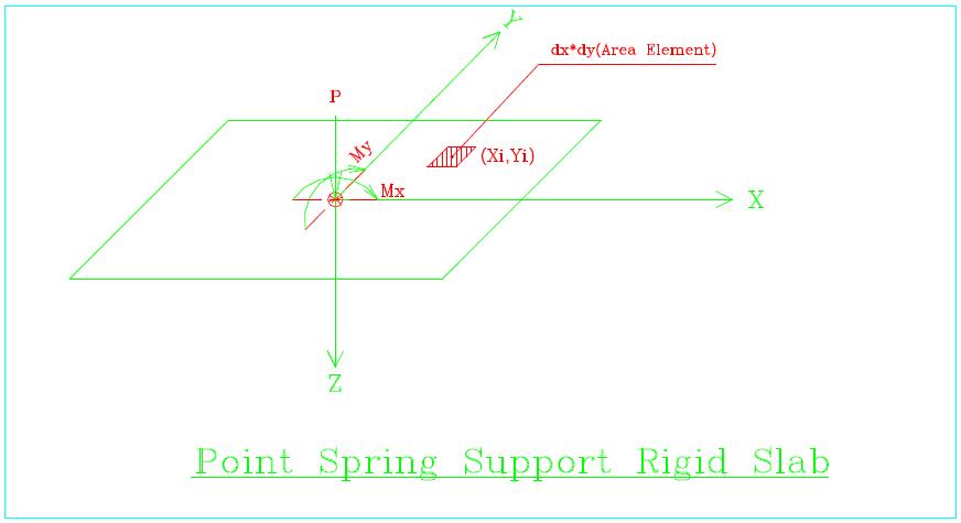
Point Spring Support Rigid Slab,Figure 2-1-1,Consider a rigid flat plate as shown in the above figure. Before loaded, it locates at z = 0. A point load (P, Mx, My) now applies at the Origin. With the normal assumption concerning plane deformation in "Strength of Materials", plane should be remain plane after deformation. Let the equation for the plane as; Figure 2-1-1
Effect on any point on the plane is in direct proportion to z (due to the assumption of elastic behaviour), so
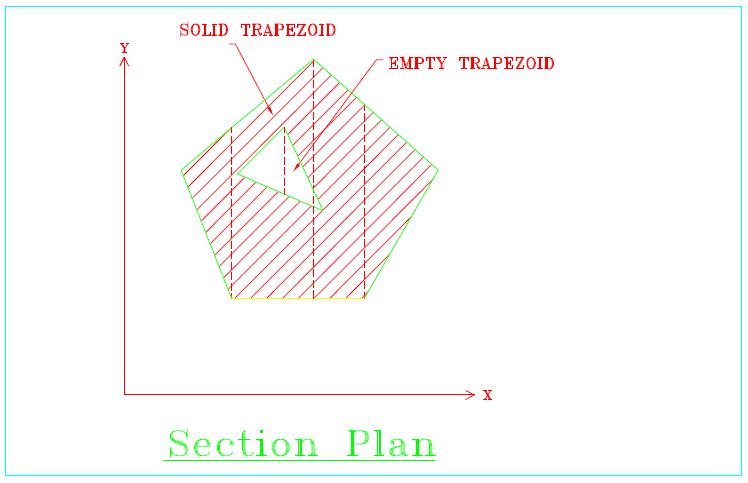
where, ß is the proportional constant. For force equilibrium, For any arbitrary plane shape such as that figure in below,It can be divided (either exactly or approximately) into finite number of elements as figure below:
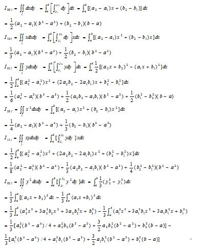
Shown by trapezoids (including triangle, sometimes). Such elements are solid and some are hollow. Perform integration on each trapezoid individually and sum them up (solid trapezoid taken position integral value and hollow trapezoid taken negative integral value). The solution of the whole shape can be obtained.
Expand formular 2-1-3 we get:
The plan is divided as n trapezoids, The above equation become as
Where, when fi = 1, it is corespondent to solid trapezoid; when fi = -1, it is to hollow trapezoid. The segmental integration of each trapezoid as;
If P, Mx, My are known, solving formula (2-1-5) will get the values of a, b, c. Substitute back to formula (2-1-2) will get the positive stresses at any point of the plane
In contrast, if the stress distribution in the plane is known (ie a, b, c are known), then the internal force P, Mx, My can be directly computed by Formula (2-1-2).
2. 2 The internal forces of the section are obtained from the known strain and elastic - plastic constitutive model (P,Mx^ My)
Assuming that the section is still flat after deformation, the section strain is expressed by the following equation:
e =a x+b y+c (Plane equation)
Shown figure as below, Stress in Segment or 2
P= ∫h dA
Mx= ∫f x dA (Bending moment along x)
My= ∫g y dA (Bending moment along y) For any sectional shape, the above formula can be solved by the method of Section 2. 1
To cumulate the P, Mx and My Corresponding to all line segments on the constitutive model of the various materials (corresponding to different areas on the section) (note that some line segments do not correspond to the area on the section where P, Mx and My are zero), you can get the total internal on the whole section under the above strain:
Nt、Mxt and Myt Note: The existing PC can complete calculation of the 30,000 section of the strain or cumulative internal force in one second, so the operation takes very little time. 2. 3 Derivation of Actual Elastic - Plastic Strain
In each round of structural analysis of the elasto-plastic analysis, the members have their own modulus of elasticity (defined in the BCD file). Its internal forces from calculation are P, Mx and My. As sescribed in the last section, the corresponding strain equation (see the figure as below) is
ε=a x+b y+c
(2-3-1)
The moment of inertia of the section along the x-direction of the section:
Iyy=Iyy0 ka
Where C 1 and C 2 are the first and second natural frequencies of the structure, respectively, and i 1 and i 2 are the damping ratios corresponding to the first and second modes.
Superstructure part: The nodes formed by the intersections of the column, wall, brace, interfloor-sub-structure and the upper and lower floor (floor plate and beam). Foundation part: The nodes formed by the intersections of the column, wall, brace, interfloor-sub-structure at the bottom of tower and pile cap, foundation beams , tie beams between pile caps. The node that does not belong to the above is the secondary node, and the stiffness and mass of all the secondary nodes will be condensed to the main node. TowerPeak uses the Wilson-0 method of the direct integration method to solve the system motion equation. The simple calculation steps are as follows: (1) Form the stiffness matrix [K], the mass matrix [M] and the damping matrix [C].
(2) Determine the initial value (all set to zero). (3) Select the time step At (defined in the EPA file), calculate the integral constant (take 0 = 1.4):
A O=6/( 0 At)2, a 1=3/(0 At), a2=2 a 1, 03= 0At/2,
a 4= A O/ 0 , a5=-a2/0, A 6=1-3/0, a 7= A t/2, a 8= A t2/6
(4) For each time step At, an effective stiffness matrix is formed:
[K'] = [K]+ QO [M]+ a 1
[C] = [K]+ QO [M]+ 01
(a[M] + P[K]) = (1+ cuP) [K] + ( a o+ a 1 a ) [M]
(5) Decomposite each [K'] according to method in Appendix A (6) Calculate the effective load at time t'= t + 0At (the previous time is t, the same below) :
[F'] t- =[F] t'+[M]( a o[D]t+ a 2 [S] t +2[A] t) + [C]( a [D] t +2[S] t + a3 [A] t)
And add [P] and the additional bending moments Mxx=Pv*dy, Myy=Pv*dx due to the deflections at time t (P- A effect),
where Pv is the vertical component of the long-term load,
and dx, dy (dx, dy, dy) is the displacement in the x,y direction at time t.
(7) Find the displacement [D] t- at time t'= t + 0At
(8) Calculate the acceleration, velocity and displacement at time t + At: [A']=Q4([D']-[D])+ Q 5[S]+ Q6[A]
[S'] = [S]+ a?([A'] + [A])
[D'] = [D]+ At [S]+ a 8([A']+2[A])
Where: [A'], [S'], and [D'] are the acceleration, velocity, and displacement at time t + A t respectively;
[A], [S], and [D] are the acceleration, velocity, and displacement at time t respectively.
2. 5 The iterative process caused by the reduction of structural stiffness The general building structure is divided into floors, beams, columns (including brace), wall, sub-structure between the floors (rod system), the pile cap, foundation beam, tie beams between the pile and pile, see Figure 1 -1 and Figure 1-2, the original stiffness matrix for each substructure is denoted by:
Floor plate+beam: [Kf] Sub-structure between the floors: [Ke]
Wall: [Kw]
Pile cap+foundation beam: [Kc]
Sort the above nodes from secondary nodes to main nodes and then condense secondary nodes into main nodes. The remained stiffness matrix and the operator Floor plate+beam: [Kf'], [Ke'], Pile cap+foundation beam: [Kc'], The original matrix equation of each substructure (the right side of the equation is the load matrix):
[Kw][Xw] = [Bw]
[Ke][Xe] = [Be]
[Kf][Xf] = [Bf] (2-5-1)
[Kc][Xc] = [Bc]
[Ks][Xs] = [Bs]
The condensed matrix equation of each substructure (right side of the equation is the load matrix):
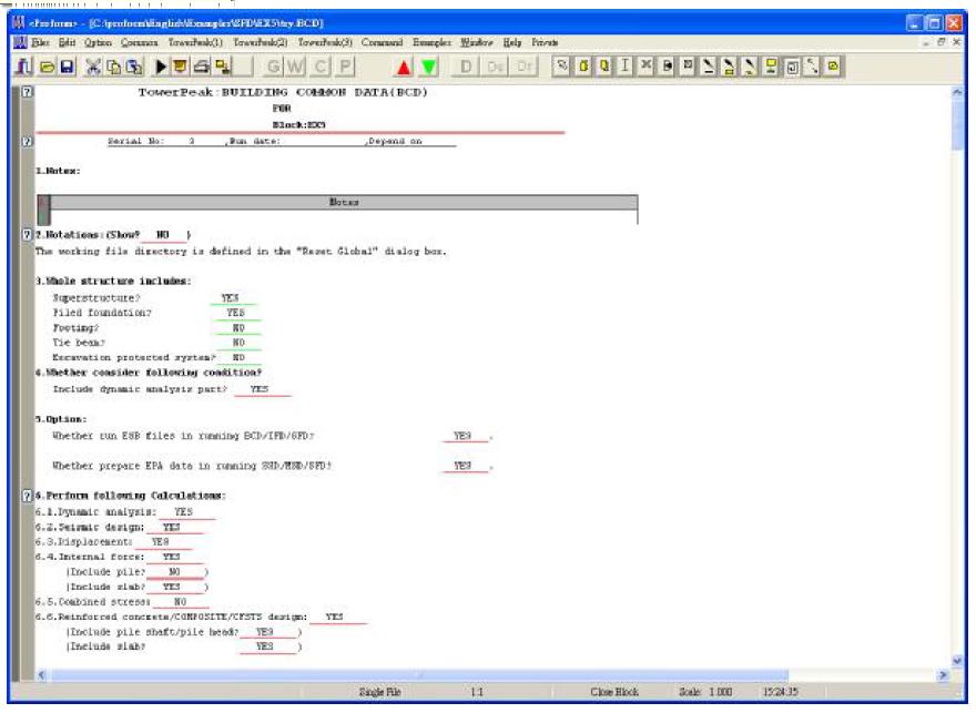
[Kw'][Xw]=[Bw'], [Bw']= Chapter 3 Calculation and Operation Flow 3.1 Set the BCD file as follows
Figure 3-1
[C]= a [M] + ft [K]
Where a , ft is the Rayleigh damping constant, determined by the natural frequency of the first and second vibration modes:
a=2«l«2 (^1«2-^2«l) / («2«2-"l"l)
ft =2 (^2«2-^1«l) / («2«2-"l"l)
Where «1 and «2 are the first and second natural frequencies of the structure, respectively, and i 1 and i2 are the damping ratios corresponding to the first and second modes.
The combination of long-term loads is used in the BCD file, as shown below:
a 0=6/(0 At) , a1=3/(9At), a 2=2 a 1, 13= 9A t/2,
a 4= a o/0, a5=-a2/0, a 6=1-3/ 0 , a 7= A t/2, a 8= A t2/6
[K'] = [K] + ao [M]+ax [C] = [K]+ao [M] + ax (a[M] + P[K]) = (1+a10) [K] + ( a 0+ a ! a )[M]
[F'L- =[F]t' +[M]( a o[D]t+ a 2 [S] t +2[A] t) + [C]( a, [D] t +2[S] t + D3 [A] t)
Where, [F] t 'includes the inertia force generated by the acceleration at time t' and the basic static load described at point 2.
[A' ] = a 4([D' ]-[D])+ a5[S]+ a 6[A]
[S'] = [S]+ a?([A'] + [A])
[D'] = [D]+ At [S]+ a8([A']+2[A])
Where, [A'], [S'] and [D'] are the acceleration, velocity and displacement at time t + At, respectively;
[A], [S] and [D] are the acceleration, velocity and displacement at time t, respectively.


![]() (2-1-1)
(2-1-1)
![]() (2-1-2)
(2-1-2) (2-1-3)

 (2-1-4)
 (2-1-5)


σ=d ε+e (d>0 for Segment 1, 2, d<0 for Segment 2)
=d(a x+b y+c)+e
=f x+g y+h
It can be seen that the stress plane is also a plane equation.
The strain of the segment 1 or 2 is now integrated into the stress of the corresponding region in the strain plane, obtained

The strain and material constitutive model (defined in the EPA file) is then used to calculate the elastic-plastic reaction forces P ', Mx' and My 'of the section according
to section 2.2, and the corresponding strain (assumed to be plane) The equation is
ε´=a´ x+b´ y+c´ (2-3-2)
Since the strain produced by P', Mx' and My' is generally less than that by internal forces P, Mx and My. In order to close to or equal to P, Mx and My, the actual strain (called the "true elastic-plastic strain") is becomed as below
ε" =a" x+b" y+c"
(2-3-3)
Where,a"=a ka; b"=b kb; c"=c kc
(ka、kb、kc is not less than 1.0)
If the [strain component] method (defined in the EPA file) is used to determine the ratio of elastic-plastic strain to elastic strain, we get
ka=a / a´; kb=b/ b´; kc=c/ c´
(2-3-4)
If the [strain volume] method (defined in the EPA file) is used to determine the ratio of elastoplastic strain to elastic strain, we get
ka=kb=kc=k
Where, k is the strain volume of e divided by the strain volume of e '.
The strain volume is the sum of the absolute values of the corresponding region integrals corresponding the negative strain and the positive strain.
If the stiffness of the member section (defined in the EPA file) is reduced by the actual elastic-plastic strain, the properties of section after reduction as follows
Area: A=Ao kc
The moment of inertia of the section along the y-direction of the section: Ixx=Ixx0 kb
Where, AO, IyyO and IxxO is the original area and moment of inertia for the entire section. And use them in the next round of calculation.
2. 4 Dynamic Response Vibration Analysis
The dynamic response vibration analysis is to find the solution from the system motion equation as below,
[M][A]+[C][S]+[K][D]=[F]+[P]
and to satisfy the initial conditions [S]=[S0],[D]=[D0],
Where :
[M]---Mass matrix of the structure
[K]---Stiffness matrix of the structure
[C]---Damping matrix of the structure, using Rayleigh damping, i.e. [C]=α[M]+β[K],
The Rayleigh damping constant is determined by the first and second natural frequencies of the structure and the corresponding two damping ratios:
α=2ω1ω2(ξ1ω2-ξ2ω1)/(ω2ω2-ω1ω1)
β=2(ξ2ω2-ξ1ω1)/(ω2ω2-ω1ω1)
[F]---The dynamic load matrix at time t, if it is caused by the seismic acceleration response spectrum, [F]=-[M]*Ag
(Where: Ag is ground motion acceleration).
[P]---Long-term load (or constant load, the combination of coefficients defined in the BCD file)
[A]--- The acceleration matrix at time t
[S]--- The velocity matrix at time t
[D]--- The displacement matrix at time t
The above matrix consists of the following nodes (called main nodes):
3.2 Run the SSD, MSD, or SFD file as shown below:

Figure 3-2-1 

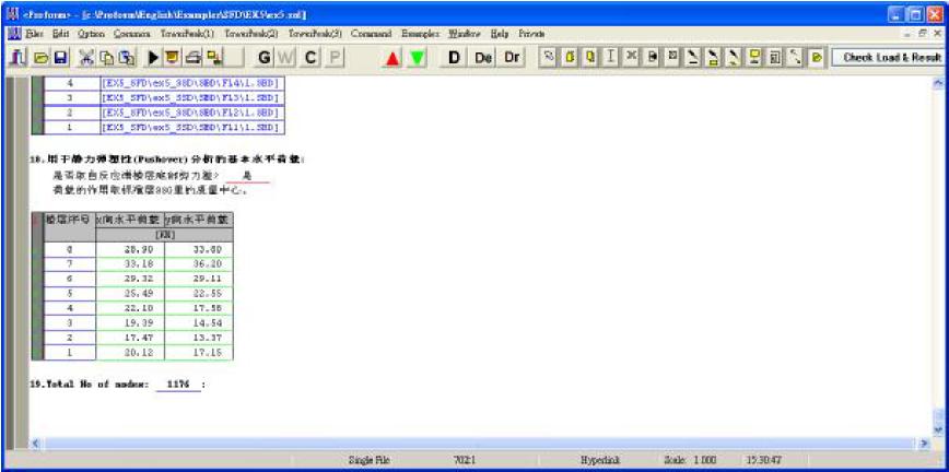
After the completion of the running, natural period of vibration, the seismic bottom shear and the basic horizontal load used to static elastic - plastic analysis and reinforcement area on the section can be obtained as shown in following four figures: 


3.3 Open an EPA file and input the relevant data below 
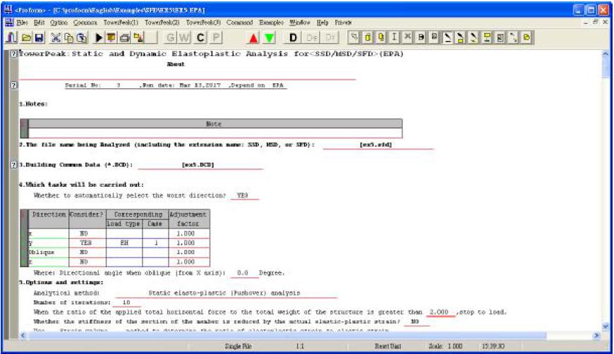
In this file, if the program automatically selects the worst direction, its direction angle is equal to the direction of the first natrural vibration period of the structure. This example is tan-1(0.582/0.083)=81. 8o
To carry out [36] of Menu->Command, you can get the results are as follows:
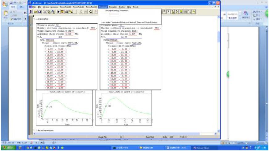
The stress-strain relationship is derived from the " Code for design of concrete structures GB50010-2010 ", the allowable shear stress of concrete is 0.8 * sqr (fcu) (fcu- Concrete strength), the allowable shear stress of steel and steel is 0.87 * fy.
3. 4 Process of static elasto - plastic analysis
1. TowerPeak automatically assigns them to nodes using the basic horizontal load for static pushover analysis using Figure 3-2-5. After the first round of calculation, TowerPeak determines the initial basic horizontal load based on the magnitude of the strain.
2. TowerPeak uses the calculated amount of steel bars to determine the distribution
of steel in the area of their own. The minimum reinforcement ratio in the EPA defined as follows:

3. Determine the horozontal load in the next round according to the input load step.
4. According to the calculated section strain, it is determined whether the section has reached the plastic hinge or broken or whether the stiffness of the section is required to reduce, and the new stiffness [Kne] of the section is calculated and compared with the original stiffness [Ke], Get [Kre] = [Ke ] - [Kne].
5. Condensing [Kri][Xi] of each sub-structure:
6. Back-substituting [Ks][Xi]=
7. The internal force and strain on the section of each member are calculated.
8. To calculate structural vibration period every [n] (set in EPA) time loads.
9. Put results for all loads in the table below:

10. To determine whether the structure has been the overall overturning damage. If not destroyed, back to step 4 to start a new round of calculation.
11. Plot the seismic impact coefficient curves of the rare earthquakes and the static thrusts and determine the structural resistance to seismic intensity:

On the above Figure, the seismic impact coefficient curve through 9 (1.4), said the structure can withstand seismic intensity of more than 9 degrees (1.4).
More than others.
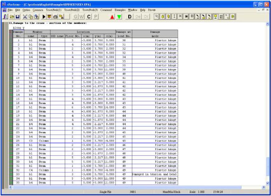
12. The display the destruction situation of members as follows:
13. Draw a stereogram (by "DXF" key to export to AutoCAD) as follows:
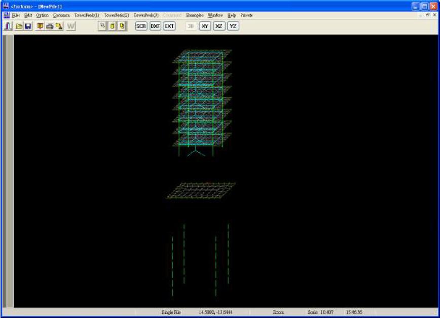

Where, the mark 7-H next to the node indicates that the node forms a plastic hinge (H) after the 7th loading, and the other symbols are as follows:
S--- Shear failure
C---Compressive bending failure
T---Tensile bending failure
3.5 Process of Elasto - plastic dynamic time history analysis
1. Create the file of "Ground Motion Acceleration Response Spectrum(ARS) " as below,

2. Same as Step 2 of Section 3. 4
3. Select the main nodes as described in Chapter. The respective stiffness matrices [K], mass matrices [M] and damping matrices [C] are formed for each standard storey and foundation. Where,

4. The dynamic response vibration analysis was performed using the Wilson-0 method (one of the direct integration methods), taking 0 = 1.4
5. 5. Determine the initial displacement [D], speed [S] and acceleration [A], all zero.
6. 6. The integral constant is calculated for each time step At:
7. For each time step At, an effective stiffness matrix is formed,
8. Decomposited for each [K'] decomposition»
9. Calculate the effective load at time t'= t + 0At (the previous time is t, the same below):
10. Find the displacement [D] t 'of the time t' = t+0At (iterations in steps 4 to 7 of step 3.4, but each time [Kr] must be multiplied by 1+ 01ft).
11. Calculate the acceleration, velocity and displacement at time t + At:
12. To determine whether the structure has been the overall overturning damage, if not, go back to step 9 to calculate.
13. Follow steps 10 through 13 of Section 3. 4 .
Appendix A
Decomposition Method of Linear Equations and Static
Condensation
As shown following figure:
For an original n-th order linear system, when the elimination of the m-row, that is, static condensation (referred to as cohesion) out m-1 elements (when m = n, that is, the linear system of the total solution) will be carried out. In the process of condensation, the decomposition of the coefficient matrix (elimination) must spend very long time. If for each new load matrix, it is necessary to decompose it once, there will be no practical value. In particular, the stiffness of the structure changes at all times. It is almost impossible to complete calculations on existing personal computers and within a limited time. Therefore, this paper will derive an operator
If user need the application program, Please visit www.towerpeak.cn or www.towerpeak.hk download and install "TowerPeak" software(included Elastoplastic Analysis :EPA),start with “sample model” of EPA.